Computer Networking
Authors: Olivier Alphand, Andrzej Duda, Franck Rousseau
2016
Important elements are displayed like this.
Exercises are displayed like this.
and their solutions!
1 Network Layer
This course provides the basic understanding of the TCP/IP networks. In this part, we consider the Network Layer.
1.1 Main notions
This part defines the elements and principles of operation of packet-switching networks.
1.1.1 What's a network?
A computer network is an interconnection of various elements that support communication of digital information.
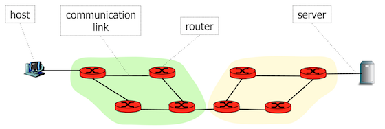
The main elements include:
- hosts: computers or devices connected to the network through communication
links. Hosts that provide useful services to other devices are called
servers.
- communication links that allow propagation of signals encoding digital information. They may use different types of communication media such as copper cables, optical fibers, radio waves.
- routers are intermediate forwarding devices that interconnect communication links.
- node: any device connected to the network.
Hosts and servers can communicate with each other over the interconnection of routers and communication links.
Networks enable communication by solving two main problems:
- Communication with everyone—how to support communication between any pair of hosts or servers?
- Everywhere communication—how to support communication over long distances and all over the world?
How to support communication between any pair of hosts?
Full mesh of all hosts is not feasible for a large number of hosts, because the number of required communication links is \(n(n-1)/2\) for \(n\) hosts. Routers enable reachability of all hosts with a partial mesh (incomplete interconnection) that requires a small number of communication links.
How to support communication spanning long distances?
We can cover long distances with a partial mesh of communication links and routers.
1.1.2 Packet switching
Digital information transmitted over the network is structured in data chunks called packets. A packet contains a header with some control information such as source and destination addresses, and a data payload with the transmitted information.
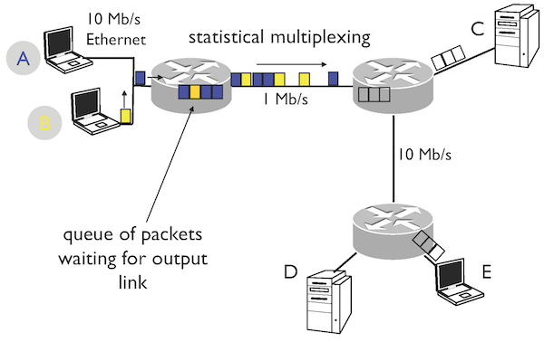
Routers forward data packets between source and destination hosts with the principle of packet switching: a router receives a packet on a link, looks up a routing table to find the link on which it transmits the packet to the next router on the path to the destination.
What is the principle of packet switching?
A router receives a packet on a link, looks up a routing table to find the link on which it transmits the packet to the next router on the path to the destination.
Why does packet switching result in a lower delay than message switching?
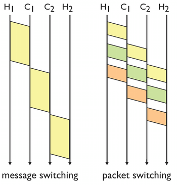
In packet switching, a message is split into packets with a limit on their size. Their transfer over several routers results in a smaller end-to-end-delay. The smaller packet size, the better improvement of the delay, but at the same time, the smaller packet size increases the overhead of the header, so there is an optimal size of packets.
1.1.3 What's the Internet?
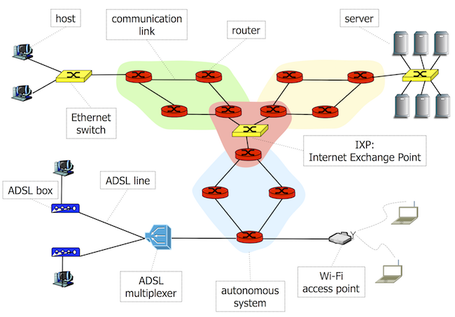
The Internet is a large scale interconnection of routers and links that enables world-wide connectivity. Routers operate according to the principle of packet switching.
Hosts connect to the first router offering Internet connectivity by means of a access network. There are differnet types of access networks: Local Area Networks (LAN) such as Ethernet, ADSL lines, or Wireless Local Area Networks such as Wi-Fi (802.11).
An autonomous system (AS) is a set of routers and links under control of a network operator on behalf of a single administrative entity with a single routing policy. The interconnection of autonomous systems forms the global Internet.
Autonomous systems exchange packets at Internet Exchange Points – high-speed local networks interconnecting border routers of autonomous systems.
The Internet Protocol (IP) defines the principles of communication: the format of packets and host addresses, and packet forwarding at routers.
What is an Internet host?
A computer or a device connected to the Internet.
1.1.4 Protocol performance
Performance mainly relates to throughput and delay.
1.1.4.1 Bandwidth, Bit Rate, Capacity, Throughput
Measured as the number of bits transmitted per time unit. Units:
- bit/s - b/s, kb/s = \(10^3\) b/s - Mb/s = \(10^6\) b/s - Gb/s=\(10^9\) b/s (kb/s means 1000 b/s and not 1024 b/s, 1 kB/s = 1000 Bytes/s = 8000 b/s).
Bandwidth is a term frequently used for Throughput or Bit Rate in the context of networks (instead of the width of a frequency band in the context of transmissions). Example: Bandwidth-Delay Product that corresponds in fact to Throughput-Delay Product.
Bit Rate is mostly used to provide the information on the raw transmission capacity at the PHY layer while Throughput refers to the transmission capacity at upper layers: e.g. useful throughput at TCP = the number of bits transferred over a TCP connection per unit time.
1.1.4.2 Latency or Delay
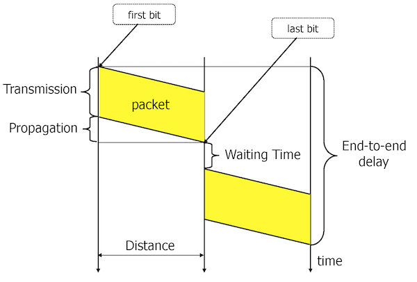
Delay or latency: it is a time interval between the beginning of a transmission and the end of the reception. If measured at a sender since the instant of transmission until receiving a response: RTT (Round-Trip Time).
To compute delay (or latency):
\(d = t_p + t_t + t_w\), where
\(d\) is the delay, \(t_p\) propagation time, \(t_t\) transmission time, and \(t_w\) waiting time (usually neglected).
\(t_p = l/v\), where
$l$is the distance and \(v\) is the speed of signal propagation:
\(v = 2.3 \times 10^8 m/s\) for copper \(v = 2 \times 10^8 m/s\) for glass (fibers) \(v = 3 \times 10^8 m/s\), speed of light in vacuum (satellites)
A useful rule of thumb for computing the propagation time is \(5 \mu s\) per km, e.g. the propagation time for the distance of 10000 km is 50 ms.
\(t_t = s/r\), where \(s\) is the number of bits to transmit and \(r\) is the bit rate.
Two hosts are connected via the Internet through 1 router. The distance between the hosts is 5000 km. All the links in the network operate at 10 Mb/s. Host A sends a series of 10 packets of 1000 Bytes to host B. What is the delay of the transfer?
11 * 0.8 ms + 25 ms = 33.8 ms.
Two hosts are connected via the Internet through 2 routers. The distance between the hosts is 10000 km. All the links in the network operate at 10 Mb/s except one in the middle at 1Mb/s. Host A sends a series of 10 packets of 1000 Bytes to host B. What is the delay of the transfer?
2 * 0.8 ms + 10 * 8 ms + 50 ms = 131.6 ms.
1.1.4.3 Bandwidth-Delay Product
Bandwidth-Delay Product is defined as:
\(\beta = C \times RTT\) \([bits]\),
where \(C\) is the bit rate (or throughput or capacity in b/s) and \(RTT\) is the Round Trip Time. It corresponds to the maximum amount of data that can be sent on a link or a network before receiving an acknowledgment ("the number of bits to fill the pipe").
If the sender can send a sufficient amount of data compared to the bandwidth-delay product, then the utilization of the link (or the network) is high and the transfer protocol achieves good performance.
Two hosts connected via Internet obtains the throughput of 1 Mb/s. The distance between the hosts is 10000 km. A data transfer protocol uses the principle of the sliding window: the sender can send \(W\) bytes without waiting for an acknowledgment. What is the minimal window size to achieve good performance?
RTT=100 ms. The minimal window size corresponds to the Bandwidth-Delay Product:
\(1 Mb/s * 100 ms = 10^5 bits=12500 B\)
1.2 Internet Protocol
There are two main versions of the IP protocol currently in use: IPv4 and IPv6. Their main difference is the address size: 32 bits in IPv4 and 128 bits in IPv6.
1.2.1 IPv4 addresses
To identify hosts on the Internet, each host has a unique address. More precisely, each network interface has an address (a host or a router may have several network interface and addresses).
An IPv4 address is a 32 bit number represented in a dotted decimal
notation, e.g. 129.88.30.11.
What makes a host unique on the Internet?
Its IPv4 or IPv6 address.
How are IPv4 addresses encoded? Give an example.
By a 32 bit number represented in a dotted decimal notation, e.g.
129.88.30.11.
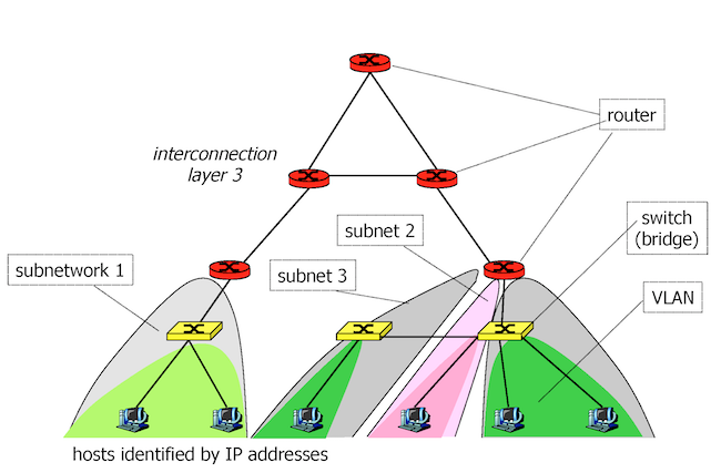
1.2.1.1 Subnetworks
A set of Internet hosts, also called subnetwork or subnet, is identified by a unique IPv4 or IPv6 address prefix. The subnetwork prefix is formed by a given number of the most significant bits of an address. The remaining part on the least significant bits is a host identifier on a given subnetwork.
Example: 129.88.30.11 and 129.88.30.12 are two Internet hosts on a
subnetwork identified by 129.88.30 11 and 12 are host identifiers.
Give an example of a subnetwork of Internet hosts with a prefix encoded on 24 bits.
129.88.30.11 and 129.88.30.12. ||129.88.30|| = 8 + 8 + 8 = 24 bits.
1.2.1.2 CIDR
The CIDR (Classless Interdomain Routing) notation gives the information on
the prefix and its bit length, e.g. 129.88.30/24.
A CIDR prefix designates a block of IP addresses by indicating the first address of the block and its length, which corresponds to the length of the field used for identifying hosts on a sub-network (IPv4 : 32 - prefix length, IPv6 : 128 - prefix length).
Exemple :
129.88.30/24represents a block of 256 addresses (\(2^8\), \(8 = 32 - 24\)) starting at129.88.30.0.129.88.30/23represents a block of 512 addresses (\(2^9\), \(9 = 32 - 23\)) starting at129.88.30.0.
CIDR allows aggregation of address blocks: e.g. blocks 129.88.30/24 and
129.88.31/24 can be represented as one 129.88.30/23 block.
What does 129.88.80/22 mean?
129.88.80/22 represents the prefix of subnetwork 129.88.80 on 22 bits –
a block of 1024 addresses starting at 129.88.80.0.
1.2.1.3 Aggregation
Assume that the network needs to maintain the information on how to route
packets to subnetworks 129.88.30/24 and 129.88.31/24 (the information on
the next-hop router used for forwarding packets to the sub-networks). Instead of
handling two routing entries of 129.88.30 and 129.88.31, the network can
aggregate them into one prefix 129.88.30/23 and handle only one entry in
routing tables. In this way, routers need to know about less routes.
Why address aggregation is important?
Because it reduces the size of routing tables and minimize network resource consumption.
What is the aggregation of 197.132.116.0/24 and 197.132.117.0/24?
197.132.116.0/23
1.2.1.4 Netmask
An alternate way of representing subnet prefixes is to specify an address and a netmask.
A netmask is a 32 bit word with \(n\) high-order bits set to 1.
Netmasks are represented in dotted decimal notation like addresses:
e.g. 255.255.255.0 corresponds to /24 prefix.
The prefix results from applying AND bitwise operation to the address and
the netmask. Example: 129.88.30.11 AND b11111111111111111111111100000000
gives 129.88.30.00 that corresponds to prefix 129.88.30/24.
What is the netmask, the prefix, and the host identifier for the address 129.132.119.77
and the prefix size of /26 ?
Netmask: 255.255.255.192, prefix: 129.132.119.64, host id.: 0.0.0.13
What is the netmask corresponding to the prefix /4? /22?
240.0.0.0, 255.255.252.0
What is the prefix corresponding to : address 0.0.0.0, netmask 0.0.0.0?
What is this prefix?
/0 - all addresses in the IPv4 address space.
This prefix is used in routing tables for a default route - the route used
when there is no other more specific routes.
1.2.1.5 Address classes
Before CIDR, the length of prefixes was fixed:
- Class A -
/8: range0.0.0.0to127.255.255.255, - Class B -
/16: range128.0.0.0to191.255.255.255, - Class C -
/24: range192.0.0.0to223.255.255.255. - There are also two other classes:
- Class D - range
224.0.0.0to239.255.255.255
for IP Multicast and
- Class E - range
240.0.0.0to255.255.255.254, reserved.
- Class D - range
1.2.1.6 Special Addresses
0.0.0.0- this host, on this network0.hostId- specified host on this net255.255.255.255- limited broadcast (not forwarded by routers)subnetId.all 1- broadcast on this subnetsubnetId.all 0- Unix BSD used it for broadcast on this subnet (obsolete)127.x.x.x- loopback (packets sent to this address will be received
by our interface without going to the network)
10/8,172.16/12,192.168/16- reserved prefixes for internal use (Intranet)169.254/16- link-local (zeroconf)
When assigning addresses to hosts on a subnetwork, we need to take into
account two addresses that are not useable for hosts (subnetId.all 1 and
subnetId.all 0). A router connected to a given subnetwork will also need
an address within the subnetwork (by convention, we assign high numbers
to routers and low numbers to hosts).
What is the limited broadcast address?
255.255.255.255, limited, because routers do not forward broadcast packets.
What is the address for broadcast on subnet 192.168/16? and for
BSD?
192.168.255.255, BSD: 192.168.0.0.
What is the loopback address? Example?
127.x.x.x, example: 127.0.0.1
What are the reserved prefixes for intranets?
10/8, 172.16/12, 192.168/16
What is the minimal prefix (containing the smallest number of addresses) required for assigning addresses to a subnetwork with 30 hosts and 1 router.
/26: 30+2+1=33 addresses required for the subnet, so the next power of 2
is 64 and the prefix length is 32-6=26.
What is the number of useable addresses (the addresses that can be
used for interfaces of hosts or routers on a given subnetwork) for a prefix /15?
\(2^{17}-2 = 131070\)
1.2.2 Packet forwarding
This part explains how routers forward packets based on destination addresses.
1.2.2.1 Routing Table
To forward packets, a node needs to have the information about where to send a packet so that it will reach the destination. A routing table provides this information in the following form:
+-+-+-+-+-+-+-+-+-+-+-+-+-+-+-+-+-+-+-+-+-+-+-+-+-+-+-+-+-+-+-+-+-+
| Destination address | Netmask         | IP address of Next Hop  |
+-+-+-+-+-+-+-+-+-+-+-+-+-+-+-+-+-+-+-+-+-+-+-+-+-+-+-+-+-+-+-+-+-+
| 0.0.0.0             | 0.0.0.0         | 129.88.30.254           |
| destinationAddr1    | 255.255.255.000 | 129.88.30.254           |
| destinationAddr2    | 255.255.255.000 | 129.88.48.254           |
We can interpret the information in the table as follows: if the destination address of the packet matches the destination address or prefix in the table, forward the packet to Next Hop.
The first entry in the table is called DEFAULT: it matches any destination.
You can inspect the table with a command such as netstat on Unix or route on Windows.
What is a route?
A sequence of routers between the source and destination hosts.
What is Next Hop?
The router to which a node needs to forward a packet to follow a given route.
What is the prefix of DEFAULT (an entry that matches all addresses)?
0/0 or 0.0.0.0/0.
How DEFAULT (an entry that matches all addresses) is expressed as an address and a netmask?
address: 0.0.0.0 netmask: 0.0.0.0.
1.2.2.2 Physical Interface Table
+-+-+-+-+-+-+-+-+-+-+-+-+-+-+-+-+-+-+-+-+-+-+-+-+
| Interface | IP Address      | Netmask         |
+-+-+-+-+-+-+-+-+-+-+-+-+-+-+-+-+-+-+-+-+-+-+-+-+
| en0       | 129.88.30.0     | 255.255.255.000 |
| en1       | 129.88.48.0     | 255.255.255.000 |
The table provides the information about the prefix of the subnetwork to which the node is directly connected so sending a packet to any node on the subnetwork consists of encapsulating the packet in a frame of a link-layer such as the Ethernet, and sending the frame to the destination node.
You can inspect the physical interface table with the command ifconfig on Unix and ipconfig on Windows.
1.2.2.3 Packet forwarding algorithm
Hosts and routers follow the rules below for forwarding a packet with
destination address destAddr:
- Direct Case: if
destAddrbelongs to the same prefix as the prefix assigned to one of the network interfaces, send the packet directly over the interface in a link-layer frame, - Indirect Case: otherwise, lookup the routing table for a prefix
matching
destAddr, find the next router (Next Hop), and send the packet to it.
More specifically:
Let destAddr is the address in the packet to forward, destinationAddr is
an address in the routing table.
- Case 1: a host route exists for
destAddr:- for every entry in the routing table
- if (
destinationAddr= =destAddr)- then send to Next Hop from the entry; leave
- Case 2:
destAddris on a directly connected subnetwork (= on-link):- for every physical interface IP address
Aand netmaskNM - if (
A&NM= =destAddr&NM)- then send directly to
destAddr; leave
- then send directly to
- for every physical interface IP address
- Case 3: a network route exists for
destAddr:- find the longest prefix that matches
destAddrin the routing table - then send to Next Hop from the entry; leave
- find the longest prefix that matches
- Case 4: use default route:
- send to Next Hop from the DEFAULT entry; leave
What is a host route?
A route that matches the destination address (/32 prefix).
How to forward a packet to a host on a directly connected subnetwork?
Send to the destination host in a frame using the link.
1.2.3 IPv4 details (RFC 791)
This part provides the details of the IPv4 protocol.
1.2.3.1 Header fields
 0                   1                   2                   3
 0 1 2 3 4 5 6 7 8 9 0 1 2 3 4 5 6 7 8 9 0 1 2 3 4 5 6 7 8 9 0 1
+-+-+-+-+-+-+-+-+-+-+-+-+-+-+-+-+-+-+-+-+-+-+-+-+-+-+-+-+-+-+-+-+
|Version|  IHL  |Type of Service|          Total Length         |
+-+-+-+-+-+-+-+-+-+-+-+-+-+-+-+-+-+-+-+-+-+-+-+-+-+-+-+-+-+-+-+-+
|         Identification        |Flags|      Fragment Offset    |
+-+-+-+-+-+-+-+-+-+-+-+-+-+-+-+-+-+-+-+-+-+-+-+-+-+-+-+-+-+-+-+-+
|  Time to Live |    Protocol   |         Header Checksum       |
+-+-+-+-+-+-+-+-+-+-+-+-+-+-+-+-+-+-+-+-+-+-+-+-+-+-+-+-+-+-+-+-+
|                       Source Address                          |
+-+-+-+-+-+-+-+-+-+-+-+-+-+-+-+-+-+-+-+-+-+-+-+-+-+-+-+-+-+-+-+-+
|                    Destination Address                        |
+-+-+-+-+-+-+-+-+-+-+-+-+-+-+-+-+-+-+-+-+-+-+-+-+-+-+-+-+-+-+-+-+
|                    Options                    |    Padding    |
+-+-+-+-+-+-+-+-+-+-+-+-+-+-+-+-+-+-+-+-+-+-+-+-+-+-+-+-+-+-+-+-+
The header of an IPv4 packet has the following fields:
- Version Number
- four bits specifying the IP protocol version of the datagram. Two versions currently coexist: IPv4 and IPv6.
- Header Length (IHL)
- the packet header may contain a variable number of options so we need the information about the header length. The minimal header without option is 20 bytes.
- TOS (Type of Service)
- initially specified the requested type of service for the packet: priority (0 - normal, 7 - control packets), short delay (for applications such as telnet), high throughput (FTP), high reliability (SNMP), low cost (NNTP). Currently, the TOS field supports DiffServ (Differentiated Services): 1 byte codepoint defining a QoS (Quality of Service) class: Expedited Forwarding (EF) - minimize delay and jitter, Assured Forwarding (AF) - four classes and three drop-precedence (12 codepoints).
- Length
- total length of the packet (header and data payload) in bytes. The field on 16 bits allows encoding the theoretical maximum size of 65,535 bytes, but IP packets are usually limited to the maximal size of the link-layer data frame, e.g. if a host is connected to the Ethernet, it will send its packets in a frame limited to 1,500 bytes. Any subnetwork should support transporting packets of the minimal size of 576 bytes (512 bytes of the data payload and 64 bytes of the header, 60 bytes being the size of the maximal header).
- Identifier
- used in fragmentation. A unique value assigned by the sender to assemble the fragments of a packet.
- Flags
- used in fragmentation. Values: bit 0 - reserved, must be zero; bit 1: (DF) 0 = May Fragment, 1 = Don't Fragment; bit 2: (MF) 0 = Last Fragment, 1 = More Fragments.
- Fragment Offset
- used in fragmentation. It indicates where in the packet this fragment belongs. The fragment offset is measured in units of 8 octets (64 bits). The first fragment has offset zero.
- Time-To-Live (TTL)
- indicates the maximum time the packet is allowed to remain in the Internet. Initially, the time was measured in seconds, currently, each router decreases the TTL by one. If the TTL field reaches 0, the router drops the packet and sends an ICMP packet to the source.
- Protocol
- indicates the next level protocol that will process the data payload. Example values: 6 - TCP, 17 - UDP (cf. RFC 1700 for all possible numbers).
- Header Checksum
- checksum on the header only. As some header fields change (e.g. TTL), the checksum is recomputed and verified at each router. The checksum field is the 16 bit one's complement of the one's complement sum of all 16 bit words in the header. For purposes of computing the checksum, the value of the checksum field is zero.
- Source and Destination IP Addresses
- 32-bit IP address of the source and final destination.
- Data (payload)
- contains the data to be delivered to the next layer protocol at the destination.
Why the Header Length?
The packet header may contain a variable number of options so we need to have its length.
How to know the size of the data payload?
Total length of the packet - Header Length.
Why packets are usually 1500 bytes?
Because they fit the maximal data size of an Ethernet frame.
Why TTL?
To drop a packet in case of a routing loop.
How a node knows the protocol that needs to process the data payload?
Protocol field.
1.2.3.2 Options: extend the information in the header
- Strict Source Routing: specifies the list of all routers to the destination,
- Loose Source Routing: specifies the list of some routers to the destination,
- Record Route: used to trace the route a packet takes,
- Timestamp Route: used to trace the route a packet takes and the instants of crossing routers,
- Router Alert: alerts transit routers to more closely examine the contents of an IP packet (used by IGMP or RSVP for processing a packet, cf. RFC 2113).
1.2.3.3 MTU (Maximum Transfer Unit)
MTU is the maximum amount of data that a link-layer frame can carry. The MTU of a link-layer protocol gives a limit on the length of an IP packet that may cross the link (e.g. 1500 bytes for Ethernet).
1.2.3.4 Fragmentation
When a router want to forward an IP packet over a link with an MTU smaller than the packet size, it needs to fragment the packet: transform a large packet into a series of smaller ones called fragments. The destination reassembles the fragments into the original packet before delivery to the next protocol layer.
Example: a packet of 1400 bytes of data needs to be fragmented before crossing a link with the 620 byte MTU.
L: Length, I: Identification, MF: More Fragment flag, Of: Offset
Initial packet: L= 1420, I=567, MF=0, Of=0
Fragments:
- L= 620, I=567, MF=1, Of=0
- L= 620, I=567, MF=1, Of=75 (8*Of=600)
- L= 220, I=567, MF=0, Of=150 (8*Of=1200)
Based on the information, the destination can reassembly the original packet.
A packet of 1400 bytes of data needs to be fragmented before crossing a link with the 980 byte MTU. What are the values of L, I, Of?
- L= 980, I=567, MF=1, Of=0
- L= 460, I=567, MF=0, Of=120
1.2.3.5 ICMP (Internet Control Message Protocol)
Routes and hosts use the ICMP protocol to report an error in packet processing: a packet cannot reach its destination, when a router drops a packet, or a router can notify a host to send traffic on a shorter route.
ICMP messages are encapsulated in IP packets.
ICMP messages have a type, a code field, and contain the first eight bytes of the IP packet that caused the generation of the ICMP message.
Main ICMP messages:
Type        Code		Description

0           0         Echo Reply (ping)
3           0-15      Destination Unreachable (network, host, protocol, port)
5           0-3       Redirect
8           0         Echo Request (ping)
11          0         Time Exceeded
Other ICMP messages:
Type        Code		Description

9           0         Router Advertisement
10          0         Router Solicitation
12          0         Bad IP Header
13          0         Timestamp
14          0         Timestamp Reply
15          0         Information Request
16          0         Information Reply
17          0         Address Mask Request
18          0         Address Mask Reply
1.2.3.6 Commands based on ICMP
Ping command generates an ICMP Echo Request message to a destination that replies with an ICMP Echo Reply message.
Traceroute command discovers the IP addresses of the intermediate routers towards a destination: Traceroute generates an IP packet with a UDP segment to a destination and sets TTL=1. The first router on the path to the destination decrements TTL that becomes 0 so it drops the packet and sends an ICMP Time Exceeded message to the source. Then, Traceroute generates an IP packet with TTL=2 to discover the second router and so on. The destination replies with an ICMP Destination Unreachable message, because the UDP segment uses a non-existent port number.
1.2.4 Address Resolution Protocol (ARP)
Packet forwarding to the next hop over the route to the destination requires the knowledge of the MAC address (also called a physical address) corresponding to the IP address of the Next Hop: a node needs to send the packet encapsulated in a frame of a link-layer such as the Ethernet for instance, so it needs to know the MAC destination address.
Node dynamically learns the MAC destination address by means of the Address Resolution Protocol (ARP): it sends a broadcast ARP Request packet to all hosts/routers connected to a given LAN. The packet includes the IP address for which we want to know the MAC address. The node that recognizes its IP address replies with a unicast packet containing its MAC address.
ARP maintains a table with the mappings of IP addresses to link-layer addresses. An ARP entry is deleted from the table after an interval (typically 20 minutes).
Consider a network with three hosts: my.imag.fr (10.0.1.1),
dns.imag.fr (10.0.2.1), www.imag.fr (10.0.3.1) interconnected by a router
that has three interfaces: 10.0.1.254, 10.0.2.254, 10.0.3.254. my.imag.fr is
connected to the router through a switch. Assume that all hosts are
correctly configured and their ARP caches are empty. A user at my.imag.fr
executes the command: ping www. Give the temporal sequence of what happens
in the network by providing the information about addresses, frame types, IP
addresses, protocol types, and other relevant details. Use the following
notation for Ethernet addresses: E_10.0.1.1 is the Ethernet address of 10.0.1.1.
1. ARP 10.0.1.254? E_10.0.1.1 to FF:FF:FF:FF:FF:FF
2. ARP 10.0.1.254 is E_10.0.1.254, E_10.0.1.254 to E_10.0.1.1
3. IP 10.0.1.1 to 10.0.2.1, E_10.0.1.1 to E_10.0.1.254, DNS over UDP, www.imag.fr A?
4. ARP 10.0.2.1? E_10.0.2.254 to FF:FF:FF:FF:FF:FF
5. ARP 10.0.2.1 is E_10.0.2.1, E_10.0.2.1 to E_10.0.2.254
6. IP 10.0.1.1 to 10.0.2.1, E_10.0.2.254 to E_10.0.2.1, DNS over UDP, www.imag.fr A?
7. IP 10.0.2.1 to 10.0.1.1, E_10.0.2.1 to E_10.0.2.254, DNS over UDP, www.imag.fr A 10.0.3.1
8. IP 10.0.2.1 to 10.0.1.1, E_10.0.1.254 to E_10.0.1.1, DNS over UDP, www.imag.fr A 10.0.3.1
9. IP 10.0.1.1 to 10.0.3.1, E_10.0.1.1 to E_10.0.1.254, ICMP Echo request
10. ARP 10.0.3.1? E_10.0.3.1 to FF:FF:FF:FF:FF:FF
11. ARP 10.0.3.1 is E_10.0.3.1, E_10.0.3.1 to E_10.0.3.254
12. IP 10.0.1.1 to 10.0.3.1, E_10.0.3.254 to E_10.0.3.1, ICMP Echo request
13. IP 10.0.3.1 to 10.0.1.1, E_10.0.3.1 to E_10.0.3.254, ICMP Echo reply
14. IP 10.0.3.1 to 10.0.1.1, E_10.0.1.254 to E_10.0.1.1, ICMP Echo reply
1.2.4.1 ARP message format
 0                   1                   2                   3
 0 1 2 3 4 5 6 7 8 9 0 1 2 3 4 5 6 7 8 9 0 1 2 3 4 5 6 7 8 9 0 1
+-+-+-+-+-+-+-+-+-+-+-+-+-+-+-+-+-+-+-+-+-+-+-+-+-+-+-+-+-+-+-+-+
|         Hardware Type         |         Protocol Type         |
+-+-+-+-+-+-+-+-+-+-+-+-+-+-+-+-+-+-+-+-+-+-+-+-+-+-+-+-+-+-+-+-+
|  HW@ Length   | Proto@ Length |            Opcode             |
+-+-+-+-+-+-+-+-+-+-+-+-+-+-+-+-+-+-+-+-+-+-+-+-+-+-+-+-+-+-+-+-+
|                        Sender Hard...                         |
+                               +-+-+-+-+-+-+-+-+-+-+-+-+-+-+-+-+
|          ware Address         |          Sender Proto...      |
+-+-+-+-+-+-+-+-+-+-+-+-+-+-+-+-+-+-+-+-+-+-+-+-+-+-+-+-+-+-+-+-+
|          col Address          |          Target Hard...       |
+-+-+-+-+-+-+-+-+-+-+-+-+-+-+-+-+                               +
|                        ware Address                           |
+-+-+-+-+-+-+-+-+-+-+-+-+-+-+-+-+-+-+-+-+-+-+-+-+-+-+-+-+-+-+-+-+
|                    Target Protocol Address                    |
+-+-+-+-+-+-+-+-+-+-+-+-+-+-+-+-+-+-+-+-+-+-+-+-+-+-+-+-+-+-+-+-+
1.2.4.2 ARP algorithm
ARP Request sent
Wait for reply
     if received, put target information (MAC address) into the table
 if not, repeat on timeout, increase timeout on each failure

ARP Packet received
If IP address = our address
  put the sender information into the ARP table
      reply with our Ethernet address as target
Otherwise
  if IP address in the table
     update entry
  otherwise
    do not update
Why the ARP Request is sent as a broadcast?
To reach all hosts/routers connected to the same LAN.
Why the ARP Reply is sent as a unicast?
To reach only the sender of the ARP Request.
Can we learn the MAC address of any host in the Internet using ARP?
No, we can only learn the MAC address of a host/router connected to the same LAN as we do.
If a host needs to deliver a packet to a router, does it also need to find the MAC address of the router?
Yes, the host obtains the IP address of the next hop from the routing table and it needs to find its corresponding MAC address with ARP.
1.2.5 IP Multicast
IP supports multicast communications: a multicast packet will reach all hosts subscribed to a multicast group. IP multicast is used for routing, streaming, and other application level purposes.
Class D addresses (from 224.0.0.0 to 239.255.255.255) identify
multicast groups. Some reserved addresses:
224.0.0.1- all multicast capable systems on subnet,224.0.0.2- all multicast capable routers on subnet
IP uses an open group paradigm: any host can send a packet to a group, no authorization is required for sending a packet to a group. A source host may send a packet to a group no matter if it belongs to the group or not. A host may belong to many different groups.
To receive a multicast packet, a host needs to subscribe to the group address using a specific protocol: IGMP (Internet Group Management Protocol).
Routers build a multicast distribution tree to all members of a group using a multicast routing protocol such as PIM (Protocol-Independent Multicast). If needed, routers replicate a packet for delivery to all members of a group.
To reach all hosts of a given group on an Ethernet LAN, a router encapsulates an IP multicast packet in a frame with the group destination address derived from the group IP address.
1.2.6 IPv6 (RFC 2460)
This part provides the details of the IPv6 protocol.
1.2.6.1 Header fields
 0                   1                   2                   3
 0 1 2 3 4 5 6 7 8 9 0 1 2 3 4 5 6 7 8 9 0 1 2 3 4 5 6 7 8 9 0 1
+-+-+-+-+-+-+-+-+-+-+-+-+-+-+-+-+-+-+-+-+-+-+-+-+-+-+-+-+-+-+-+-+
|Version| Traffic Class |           Flow Label                  |
+-+-+-+-+-+-+-+-+-+-+-+-+-+-+-+-+-+-+-+-+-+-+-+-+-+-+-+-+-+-+-+-+
|         Payload Length        |  Next Header  |   Hop Limit   |
+-+-+-+-+-+-+-+-+-+-+-+-+-+-+-+-+-+-+-+-+-+-+-+-+-+-+-+-+-+-+-+-+
|                                                               |
+                                                               +
|                                                               |
+                         Source Address                        +
|                                                               |
+                                                               +
|                                                               |
+-+-+-+-+-+-+-+-+-+-+-+-+-+-+-+-+-+-+-+-+-+-+-+-+-+-+-+-+-+-+-+-+
|                                                               |
+                                                               +
|                                                               |
+                      Destination Address                      +
|                                                               |
+                                                               +
|                                                               |
+-+-+-+-+-+-+-+-+-+-+-+-+-+-+-+-+-+-+-+-+-+-+-+-+-+-+-+-+-+-+-+-+
The header of an IPv6 packet has the following fields:
- Version Number
- four bits specifying the IP protocol version of the datagram.
- Traffic Class
- QoS on aggregates - the DiffServ 1 byte codepoint.
- Flow Label
- identifies packets belonging to the same flow, per flow QoS.
- Payload Length
- length in bytes of the packet payload (data following header).
- Next Header
- indicates the type of the header immediately following the basic header.
- Hop Limit
- like TTL - decremented each time the packet is forwarded, packet discarded when it reaches zero.
- Source and Destination Addresses
- 16 byte addresses.
1.2.6.2 Extension headers
- Hop by Hop
- must be processed by each node on the path to the destination.
- Destination
- information for the destination host.
- Fragment
- similar to IPv4, but only the source may fragment. Packets exceeding the maximal size are dropped by routers and an ICMP message is sent to the source.
- Authentication
- support of IPSec.
- Encapsulating Security Payload
- support of IPSec.
1.2.6.3 IPv6 addresses
Addresses are 16 bytes long = 128 bits, 4 times more bits than in IPv4 (number of addresses: \(3.4 \times 10^{38}\)).
Notation:
- 8 groups of 16 bits in hexadecimal, 4 hex digits separated by ":"
- leading zeros of each group can be ignored
- one group of zeros can be replaced by "::"
- CIDR notation as in IPv4: prefix/len
Examples:
2001:660:5301:26:210:83ff:fe35:3404/64fe80::210:83ff:fe35:3404::1/128(loopback)2000::123:4567:89AB:CDEFFF05::1:3
Address types and scope:
- unicast as in IPv4,
- anycast: an address shared by several hosts - a packet is sent to the "nearest" host.
- multicast: prefix
FF00::/8(there is no broadcast in IPv6) - IPv4 addresses in IPv6: IPv4-mapped IPv6 address (
::FFFF:<IPv4 address>, e.g.::FFFF:129.144.52.38) - link-local: prefix
FE80::/10 - global addresses: reachable in the Internet, prefix
2000::/3
What is anycast?
A packet is sent to the "nearest" host.
1.2.6.4 IPv6 Multicast Addresses:
Format: 8-bit prefix 11111111 + 4-bit flags + 4-bit scope + 112-bit group ID
- flags: T=1 - permanent address
- scope is a 4-bit value that defines the scope of the multicast group: 1 Interface-Local scope 2 Link-Local scope 4 Admin-Local scope 5 Site-Local scope 8 Organization-Local scope E Global scope.
- examples:
FF02::101- all link-local NTP servers (scope = 2, NTP group = 101),FF02:0:0:0:0:0:0:1- all link-local nodes.
Solicited-Node Address:
Solicited-Node Address of the form FF02:0:0:0:0:1:FFXX:XXXX is a multicast
address computed as a function of a node unicast and anycast addresses.
A Solicited-Node Address is formed by taking the low-order 24
bits of an address (unicast or anycast) and appending those bits to the
prefix FF02:0:0:0:0:1:FF00::/104 resulting in a multicast address in the
range from FF02:0:0:0:0:1:FF00:0000 to FF02:0:0:0:0:1:FFFF:FFFF. For
example:
- the Solicited-Node multicast address corresponding to the IPv6
address
4037::01:800:200E:8C6CisFF02::1:FF0E:8C6C.
What is Solicited-Node Address?
The address of a node derived from its unicast address. Used in neighbor discovery.
1.2.6.5 ICMPv6
Replaces ICMP and ARP of IPv4.
Main ICMPv6 messages:
- Destination unreachable (type 1)
- Packet too big (type 2)
- Time exceeded (type 3)
- Parameter problem (type 4)
- Echo request/reply (type 128 and 129)
Neighbor Discovery:
- Replaces ARP, ICMP (redirect, router discovery)
1.2.6.6 Stateless autoconfiguration
IPv6 supports autoconfiguration of addresses.
1.2.6.7 Link-local addresses
A node creates a link-local address by concatenating the link-local prefix
FE80::/10 and a unique 64-bit EUI-64 (Extended Unique Identifier) IPv6
interface identifier. EUI-64 is obtained from the 48-bit MAC address: the
MAC address is first separated into two 24-bit parts. The 16-bit 0xFFFE
pattern is then inserted between these two 24-bit parts to form the
EUI-64 identifier. Finally, the seventh bit from the left (the
universal/local, U/L bit), needs to be inverted.
- Example of EUI-64:
- Ethernet address on 48 bits:
00:90:27:17:FC:0F - EUI-64 on 64 bits, 7th bit inversed:
02:90:27:FF:FE:17:FC:0F
- Ethernet address on 48 bits:
- Example of the created link-local address:
FE80::290:27FF:FE17:FC0F
1.2.6.8 Obtaining global routable address
- To obtain a global routable address, a node needs to learn its prefix using Router Solicitation and Advertisement. We assume that there is a router connected to the same link as the node.
- At boot time, a node has to join 2 special multicast groups for
each network interface:
- All-nodes multicast group:
ff02::1 - Solicited-Node multicast group:
ff02::1:ffXX:XXXX,XX:XXXXcome from the lower 24 bits of the node address
- All-nodes multicast group:
- When node A needs to learn the prefix, it sends:
ICMP Type = 133 (Router Solicitation), Src = link-local address, Dst =
all-routers multicast address (=FF02::2=), Query = Please send RA
Router responds with an ICMPv6 packet to all nodes on-link:
ICMP Type = 134 (Router Advertisment), Src = link-local address, Dst =
all-nodes multicast address (FF02::1), Data = options, subnet prefix,
lifetime
Example: if the prefix is 2001:660:5301::/48, the global routable address
is 2001:660:5301::290:27FF:FE17:FC0F.
1.2.6.9 Reachability of neighbors
Neighbor Solicitation (ICMPv6 type 135) and Neighbor Advertisement (ICMPv6 type 136) replace ARP.
To find the MAC address of neighbor B, host A sends an ICMPv6 packet:
ICMP Type = 135 (Neighbor Solicitation), Src = A, Dst = Solicited-Node
multicast of B, Data = link-layer address of A, Query = what is your link
address?
B responds with an ICMPv6 packet:
ICMP Type = 136 (Neighbor Advertisement), Src = B, Dst = A, Data =
link-layer address of B
1.2.6.10 Duplicate Address Detection (DAD)
When a node creates its link-local address, it needs to verify that it is unique by sending a Neighbor Solicitation packet to the Solicited-Node multicast corresponding to the link-local address. If there is no response, the address is unique.
- Example: if the node creates the link-local address
FE80::290:27FF:FE17:FC0F, the corresponding solicited-node multicast isFF02::1:FE17:FC0F.
1.3 Routing protocols
A routing protocol finds the best routes to all destinations. The best route means the shortest path in terms of a given metric: number of hops, delay. The protocol constructs routing tables that reflect the information on the best routes: the next router to use for forwarding a packet to a given destination over the best route.
1.3.1 Distance Vector
In the Distance Vector protocol, routers periodically advertise their Distance Vectors: \(D (k, n)\), the distance from router \(k\) to destination \(n\) (distance in terms of a metric). They estimate the distance to each neighbor \(c (i, k)\). When router \(i\) receives the Distance Vectors from all the neighbors, it chooses the best route to destination \(n\):
\(D (i, n) = \min_k (c (i, k) + D (k, n))\),
where \(c (i, k)\) is the estimated distance to neighbor \(k\).
The Distance Vector protocol suffers from counting to infinity: routers exchange vectors by increasing the distance. Two ways for solving the problem:
- Split Horizon: a router cannot advertise its route to a neighbor, if the neighbor is the next hop for a given destination. (Reverse Poisoning version: advertise its route with the distance of infinity).
- Maximal Distance: set the limit to the distance and consider it as infinity.
Examples of protocols: RIP, IGRP.
Consider a network composed of six routers \(R_i, i= 1,...,
6\) connected in a ring.
Subnetwork with prefix 1.1.1/24 is connected to \(R_1\) and subnetwork with
prefix 4.4.4/24 is connected to \(R_4\).
We neglect all other prefixes. All routers run a distance vector routing
protocol such as RIP with Split Horizon. Unless otherwise specified, the
cost of a link between two routers is 1. The cost from a router to a
directly attached network is 0.
- Give the advertisements of \(R_2\), \(R_3\), \(R_5\), and \(R_6\),
- After propagation of advertisements in the network, give the routing
tables of \(R_1\) and \(R_4\) in the form:
Destination Network, Next-Hop, Distance.
- The links between \(R_2\) and \(R_3\), \(R_5\) and \(R_6\) fail.
Give the new routing tables.
\(R_2\) : 1.1.1/24, \(d=1\);4.4.4/24, \(d=2\)\(R_3\) : 1.1.1/24, \(d=2\);4.4.4/24, \(d=1\)\(R_5\) : 1.1.1/24, \(d=2\);4.4.4/24, \(d=1\)\(R_6\) : 1.1.1/24, \(d=1\);4.4.4/24, \(d=2\)- \(R_1\) :
Destination Network Next-Hop Distance 1.1.1/24direct 0 4.4.4/24\(R_2\) 3 \(R_4\) :
Destination Network Next-Hop Distance 1.1.1/24\(R_5\) 3 4.4.4/24direct 0 - \(R_6\) can receive the advertisement of \(R_1\):
4.4.4/24, d=3 that \(R_1\) can send even when applying Split Horizon (\(R_1\) routes to4.4.4/24through \(R_2\) as the next hop, so it can advertise this route to \(R_6\)), so \(R_6\) will accept this route. However, when \(R_2\) advertises route4.4.4/24with d=\(\infty\), \(R_1\) will transfer this route to \(R_6\), and finally all routing tables will correspond to the new topology -4.4.4/24is unreachable.
1.3.2 Link State
In the Link State protocol, routers advertise the information on their links (distance, neighbor) to all routers in the network. Advertisements use the principle of flooding: a router receives a routing message on a link and forwards it over all outgoing links. In this way, all routers receive the messages of all routers and can construct the graph of the network–they know the detailed topology of the network.
To find the best routes to all the destinations, a router runs a graph optimization algorithm such as the Dijkstra algorithm for finding the Shortest Path in a graph.
1.3.2.1 Dijkstra algorithm at router A
- Initialization: PATH variable: router A (the best paths to destinations) TENT variable: empty (tentative paths)
- For each router \(N\) in PATH
for each neighbor \(M\) of \(N\)
\(c(A, M) = c(A, N) + c(N, M)\) if \(M\) is not in PATH nor in TENT with a better cost, insert \(M\) with direction \(N\) in TENT
- If TENT is empty, end. Otherwise take the entry with the best cost from TENT, insert it into PATH and go to 2.
At the end, PATH contains the tree of best paths to all destinations: the next hop and the shortest distance to all destinations.
1.3.3 External routing - BGP
The Internet is an interconnection of Autonomous Systems (AS): a collection of hosts and routers under one authority that presents a common routing policy to other ASs. Each AS runs an internal routing protocols for packet forwarding to and from its subnetworks (RIP, OSPF, IGRP). An AS advertises its prefixes to other ASs with an external routing protocol such as BGP (Border Gateway Protocol). An AS learns about all other prefixes using BGP.
A BGP router receives and advertises the information about prefixes and their attributes. One common attribute is AS_PATH: the set of AS numbers to traverse to reach an advertised destination. A BGP router makes routing decisions based on the AS_PATH attribute, network policies or rules configured by a network administrator.
2 Link Layer and Local Area Networks
In this part, we consider the Link Layer and Local Area Networks (LAN).
2.1 Link Layer
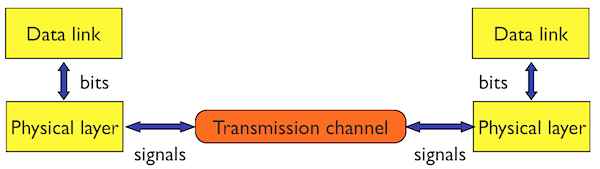
The Link Layer organizes communication between two devices directly connected by a Physical Layer that allows transmission of a series of bits.
It structures transmitted bits in frames by usually adding redundant bits for error detection (CRC). Examples: PPP.
The Link Layer also encompasses Local Area Networks (LANs) in which several devices use a common transmission medium.
The main problem addressed by a MAC (Medium Access Control) protocol is to control the access of several contending devices to a shared transmission medium (shared cable, radio channel, etc.). Different LANs use specific MAC protocols: Ethernet uses CSMA/CD, 802.11 (Wi-Fi) uses CSMA/CA.
2.1.1 PPP (Point-to-Point Protocol)
PPP provides a means for transporting packets over point-to-point links. It defines a frame format inherited from first packet switching networks synchronous transmission with error recovery (HDLC).
+----------+----------+----------+
|   Flag   | Address  | Control  |
| 01111110 | 11111111 | 00000011 |
+----------+----------+----------+
+----------+-------------+---------+
| Protocol | Information | Padding |
| 8/16 bits|      *      |    *    |
+----------+-------------+---------+
+----------+----------+-----------------
|   FCS    |   Flag   | Inter-frame Fill
|16/32 bits| 01111110 | or next Address
+----------+----------+-----------------
The PPP frame is delimited by the Flag Sequence 01111110 (hexadecimal
0x7e).
FCS (Frame Check Sequence) is computed using polynomial error detection
codes to detect corrupted frames.
Transparent operation (the possibility of sending any byte value in the
Information field) is achieved with Byte Stuffing.
The Control Escape octet is defined as binary 01111101 (hexadecimal
0x7d), most significant bit first.
Byte Stuffing:
- each Flag Sequence, Control Escape octet, and any byte value less than
0x20is replaced by a two octet sequence consisting of the Control Escape octet followed by the original octet exclusive-or'd with hexadecimal0x20.
Examples:
0x7e is encoded as 0x7d, 0x5e. (Flag Sequence)
0x7d is encoded as 0x7d, 0x5d. (Control Escape)
0x03 is encoded as 0x7d, 0x23. (ETX)
On reception each Control Escape octet is removed, and the following
octet is exclusive-or'd with hexadecimal 0x20, unless it is the Flag Sequence
(which aborts a frame).
A sender provides the following sequence to PPP:
0x7e, 0x41, 0x7d, 0x33, 0x01
What is the
sequence observed on the communication channel?
0x7d, 0x5e, 0x41, 0x7d, 0x5d, 0x33, 0x7d, 0x21
The receiver receives the following sequence:
0x7d, 0x5e, 0x41, 0x7d, 0x5d, 0x33, 0x7d, 0x21
What is the
sequence received by the protocol on top of PPP?
0x7e, 0x41, 0x7d, 0x33, 0x01
2.1.2 Ethernet
Ethernet is a wired LAN that evolved over time from the initial variant of 10 Mb/s over a coaxial cable to recent 10 Gb/s or 100Gb/s over fiber. The principle of its operation is based on random access that results in very good performance for small traffic load.
2.1.2.1 Initial variant
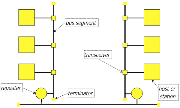
The topology is in the form of bus segments (coaxial cable): one backbone segment connected to other segments. The cable provides the shared transmission medium of the nominal throughput of 10 Mb/s that supports broadcast: a frame sent by one device will propagate over the cable to reach all other connected devices, which means that all stations receive all transmitted frames and copy to their buffers only the frames sent to them. To extend the coverage, repeaters between segments amplify the signal and retransmit on another segment. There are limitations on the segment length, the number of repeaters, and the topology that bound the total round trip time between any two stations connected to the network to \(51.2 \mu s\).
2.1.2.2 CSMA/CD
n = 0
repeat
	wait until carrier sense off
	wait for interframe gap
	transmit and detect collision
	if (collision detected) then
	   stop transmitting
	   transmit jam (32 bits)
	   n++
	if (n == maxAttempts) then
	   abort
	k = min(n, 10)
	r = random(2^k - 1)
	wait for random time (r × slotTime)
	else
		success
until (success or abort)
A station that wants to transmits, tests if the channel is already used (carrier sense on). If the channel is free, the station waits for an interval called interframe gap (\(9.6\mu s\)) and transmits the frame. While transmitting, it checks whether a collision happens (by detecting an increased power of the signal on the cable due to overlapped transmissions). In case of a collision (collision detected), the station stops transmitting the frame and transmits a sequence of random bits called a jam (32 bits). Then, it increments \(n\), the counter of collisions and chooses a random retransmission interval:
\(T = r \times slotTime\),
where \(r = random(2^k - 1)\), \(k = min (n, 10)\), and \(slotTime = 51.2 \mu s\).
Value \(r\) for subsequent collisions is the following:
- 1st collision, \(r \in [0, 1]\)
- 2nd collision, \(r \in [0, 3]\)
- 10th, \(r \in [0, 1023]\)
- 15th, stop
Another collision may happen if both stations choose the same value of \(r\), which arrives with probability \(1/2\) for the first collision, \(1/4\) for the second one, and then \(1/2^k\).
Increasing the interval for choosing \(r\) in the exponential way is called exponential backoff.
The station retransmits the frame after the retransmission interval (it follows the rules for accessing the channel: detecting channel activity, deferring until the channel is free, and eventually, waiting for an interframe gap).
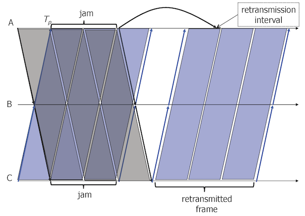
The figure illustrates how a collision is recovered:
- at time \(t=0\), both stations \(A\) and \(C\) have frames to send, they test the channel and start sending their frames, because there is no on-going transmission at this instant
- at time \(t=T_p\), when the signal of \(A\) arrives at \(C\) (and the signal of \(C\) at \(A\)) both stations detect a collision, stop their transmissions and send a jam
- after the jam, they choose random retransmission intervals:
- \(A\) chooses 1 slotTime, it defers the retransmission
- \(C\) chooses 0 slotTime, it can proceed
- \(C\) tests the channel (there is still the signal corresponding to the jam of \(A\)), waits until there is no signal and send its frame
- when \(A\) tests the channel after 1 slotTime, but there is the on-going transmission of \(C\), so it waits until the end of the frame
- \(A\) transmits after the end of the frame of \(C\) (not shown in the figure).
slotTime of \(51.2 \mu s\) guarantees that after this time, all stations receive the transmitted signal and they do not interfere with the current transmission (collisions may not happen after this interval). The value of \(51.2 \mu s\) comes from the limitation of the segment length and the maximal number of repeaters between any two stations: all the propagation delays result in a round trip time less than \(51.2 \mu s\), the value that corresponds to the transmission of 64 Bytes over 10 Mb/s. This parameter results in:
- \(51.2 \mu s\) becomes the retransmission unit: if after a collision, a station tries to retransmit after \(51.2 \mu s\), either the channel is free et it transmits, either there is ongoing transmission, so it will defer until its end (we avoid another collision),
- if a station has already sent 64 Bytes, the channel is acquired by the station–there will be no collision during the transmission,
- if there is a collision, the rest of the unsuccessful transmission will have the size < 64 Bytes. Any frame with the size < 64 Bytes is invalid.
Three stations A, B, C are connected to 10 Mb/s Ethernet. They are placed at the distance of: A-B 1km, B-C 1km, A-C 2km. At \(t=0\), stations A and C have a minimal sized frame to send and there is an ongoing transmission by B that ends at \(t=5 \mu s\). Assume that if there is a collision, both stations choose a different number of slots. Give the timeline of what happens (the instants and the events).
\(t=0\), start
| \(t=5 \mu s\), | end of B transmission |
| \(t=10 \mu s\), | A senses channel free |
| \(t=10 \mu s\), | C senses channel free |
| \(t=19.6 \mu s\), | A starts transmission after gap |
| \(t=19.6 \mu s\), | C starts transmission after gap |
| \(t=29.6 \mu s\), | signal of A arrives at C, collision detection |
| \(t=29.6 \mu s\), | signal of C arrives at A, collision detection |
| \(t=32.8 \mu s\), | end of jam by A, choose \(r=0\) |
| \(t=32.8 \mu s\), | end of jam by C, choose \(r=1\), come back at \(t=84 \mu s\) |
| \(t=42.8 \mu s\), | last bit of jam arrives at A |
| \(t=42.8 \mu s\), | last bit of jam arrives at C |
| \(t=52.4 \mu s\), | A starts transmission after gap |
| \(t=52.4 \mu s\), | A starts transmission after gap |
| \(t=84.9 \mu s\), | C senses channel busy |
| \(t=103.6 \mu s\), | end of A transmission |
| \(t=113.6 \mu s\), | last bit of A transmission arrives at C |
| \(t=123.2 \mu s\), | C starts transmission after gap |
| \(t=174.4 \mu s\), | end of C transmission |
| \(t=184.4 \mu s\), | last bit of C transmission arrives at A |
2.1.2.3 Frame format, addresses
Ethernet 2 encapsulation:
 0                   1
 0 1 2 3 4 5 6 7 8 9 0 1 2 3 4 5
+-+-+-+-+-+-+-+-+-+-+-+-+-+-+-+-+
|           DST_ADDR            |
|          (6 octets)           |
|                               |
+-+-+-+-+-+-+-+-+-+-+-+-+-+-+-+-+
|            SRC_ADDR           |
|          (6 octets)           |
|                               |
+-+-+-+-+-+-+-+-+-+-+-+-+-+-+-+-+
|    ETHER_TYPE  (2 octets)     |
+-+-+-+-+-+-+-+-+-+-+-+-+-+-+-+-+
~                               ~
~           payload             ~
~       (46 - 1500 octets)      ~
+-+-+-+-+-+-+-+-+-+-+-+-+-+-+-+-+
|      CHECKSUM (4 octets)      |
+-+-+-+-+-+-+-+-+-+-+-+-+-+-+-+-+
The DST_ADDR field contains either a unicast address or a group address
(the first bit of the address = 1).
Data on Ethernet are transmitted least significant bit of the first byte first (a bug of Intel processors). Canonical representation thus inverts the order of bits inside a byte (the first bit of the address is the least significant bit of the first byte).
Addresses are represented in the hex notation: 08:00:20:71:0d:d4.
The broadcast address is ff:ff:ff:ff:ff:ff.
Exemples :
- a group address:
01:00:5e:02:a6:cf. - a multicast address for IPv4:
01:00:5e:02:a6:cf. - a multicast address for IPv6:
33:33:ff:02:a6:cf.ETHER_TYPEdetermines an upper layer protocol that will interpret the payload:0x0800(IPv4),0x86DD(IPv6),0x08060(ARP).
Why the Ethernet frame has a minimal size?
It should be longer than 64 B that correspond to \(51.2 \mu s\) needed for signal propagation all over the network.
2.1.2.4 Evolution of Ethernet
Fast Ethernet: 100 Mb/s over 4 twisted pairs.
Gigabit Ethernet: 1 Gb/s, 10Gb/s, 40 Gb/s over fiber.
Advanced cabling with twisted pair cables: interconnection with hubs - multiport repeaters - a Layer 1 interconnection element.
A hub receives a signal and retransmits it on all outgoing ports.
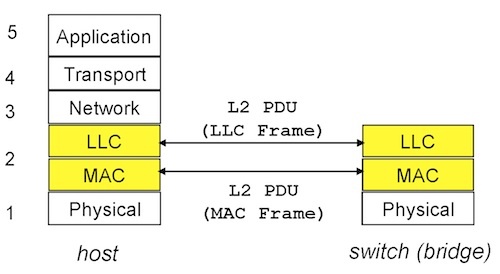
Switches interconnect stations by forwarding MAC frames to destinations based on MAC addresses - a Layer 2 interconnection element. A switch operates receives a frame, checks its validity (CRC, size) and retransmits on the outgoing port to the destination station (Store and Forward operation).
A bridge operates in a similar way, but it may interconnect heterogeneous networks, e.g. a 802.11 Access Point is a bridge between the wired Ethernet LAN and the wireless 802.11 link connecting mobile stations.
Full-duplex Ethernet: possibility of sending and receiving at the same time. No collisions possible.
Two stations A, B are connected to 10 Mb/s Ethernet with hub H. They are placed at the distance of: A-H 1km, H-B 1km, A-B 2km. At \(t=0\), station A has a minimal sized frame to send. Give the timeline of what happens (the instants and the events).
\(t=0\), start \(t=9.6 \mu s\), A starts transmission after gap \(t=14.6 \mu s\), H receives the signal and retransmits to B \(t=19.6 \mu s\), B receives the signal \(t=70.8 \mu s\), B receives the frame
Two stations A, B are connected to 10 Mb/s Ethernet with switch S. They are placed at the distance of: A-S 1km, S-B 1km, A-B 2km. At \(t=0\), station A has a minimal sized frame to send. Give the timeline of what happens (the instants and the events).
\(t=0\), start \(t=9.6 \mu s\), A starts transmission after gap \(t=14.6 \mu s\), S receives the signal \(t=65.8 \mu s\), S receives the frame and retransmits to B \(t=70.8 \mu s\), B receives the signal \(t=122.0 \mu s\), B receives the frame
2.1.2.5 Learning switches (or learning bridges)
Forwarding frames by switches (or bridges) requires forwarding tables that provides the information about the outgoing port for a given destination MAC address. Learning switches (or bridges) operates in a plug-and-play manner: they begin with the empty forwarding table and learn the location of stations (couple MAC address-port) from the sources addresses of frames sent by stations.
The problem of which port to choose for a destination address that is not yet in the forwarding table, is solved with flooding: when there is no entry in the forwarding table, the switch will replicate the frame and send the frames on all outgoing ports. Flooding solves the initialization problem, but suffers from the possibility of creating an increasing number of frames if the topology of switch (or bridge) interconnection contains a loop.
Two stations A, B are connected to 10 Mb/s Ethernet with switch S. They are placed at the distance of: A-S 1km, S-B 1km, A-B 2km. At \(t=0\), station A has a minimal sized frame to send. Give the forwarding table of S after receiving the frame of A.
| MAC address | outgoing port |
| ------------- | ---------------------- |
| address of A | port connected to A |
2.1.3 802.11 (Wi-Fi)
IEEE 802.11 standard defines wireless LANs, a network that provides connectivity to mobile stations. It uses two unlicensed frequency bands:
- 802.11b/g/n: 2.4-2.483 GHz (several channels of 22 MHz)
- 802.11a: 5.15-5.725 GHz
The nominal bit rate is 11 Mbit/s for 802.11b, 54 Mbit/s for 802.11g, and 72 Mbit/s for 802.11n (on a single 20 MHz channel).
When transmission conditions are bad, a station may reduce its bit rate by using a more robust modulation, e.g. reduce from 11 Mbit/s to 5.5, 2, or 1 Mbit/s.
802.11 uses CSMA/CA access method, similar to CSMA/CD of Ethernet, but with two major differences:
- No possibility of detecting a collision during a transmission,
- Radio channels have higher error rates compared to cables. Stations will use ACKs to improve reliability.
802.11 covers a distance of the order of ~70 m indoor.
Stations consider an 802.11 network interface as Ethernet-it has the same limitations as Ethernet: the maximum data size in a frame of 1500 bytes.
Below, we use two time intervals to manage frame priority:
- SIFS short interframe space
- short time for high priority frames (ACK),
- DIFS DCF interframe space
- long time for lower priority frames (DATA).
2.1.3.1 CSMA/CA
Simple case - low load, no channel activity:
test the channel
if free,
   wait DIFS interval (long),
   if the channel free
      transmit frame
      wait SIFS interval (short)
      receive ACK
More complex case with contention of at least two stations - there is channel activity, apply Collision Avoidance: choose a random wait interval before transmission attempts:
Residual = 0

Start:
if channel used,
   n = 0
   wait until carrier sense off,
   wait DIFS interval (long)
   if the channel free
      if Residual > 0
         wait Residual
	 otherwise
         choose backoff r from Contention Window [0, Wmax]
         wait r x Slot
         if receives a transmission signal
            stop waiting, Residual = remaining Slots, go to Start:
	    otherwise
            transmit frame
            wait SIFS interval (short)
            receive ACK
CSMA/CA and preamble/header overhead make the useful throughput fairly low compared to the nominal bit rate: around 60% of 11Mb/s - 6.5Mb/s at application layer.
2.1.4 VLANs (Virtual Local Area Networks)
VLAN switches provides the possibility to create several logical LANs (Virtual LANs) over one physical infrastructure.
For instance, we can define separate VLANs for administration and for students for security reasons - there is no possibility of frame transmission between different VLANs (no layer 2 communication).
VLAN = set of stations that can communicate with each other at layer 2.
VLAN switches associate a frame with its VLAN based on:
- Explicit tagging - a VLAN tag is inserted in a frame so that a receiving switch can decide to which VLAN the frame belongs and send it to the right port. Example: IEEE 802.1Q frame with 12 bit field of a VLAN tag.
- Implicit information - VLAN ID implicitly deduced from: port number, MAC address, or layer 3 address.
To check which station belongs to a given VLAN, we can consider a broadcast frame - when a host sends a broadcast, it needs to be received by all stations/hosts belonging to the same VLAN.
2.1.5 VLAN per port
This technique allows us to define a VLAN based on the switch ports. All hosts connected to this port will belong to the VLAN assigned to the port. The administrator configures the association (port – VLAN number) in the VLAN table.
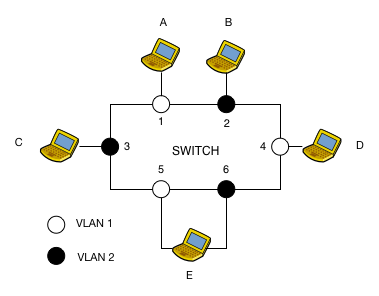
The VLAN table for the switch in the figure is the following:
+-+-+-+-+-+-+-+-+-+-+
|    VLAN TABLE     |
+-+-+-+-+-+-+-+-+-+-+
|   Port  |   VLAN  |
+-+-+-+-+-+-+-+-+-+-+
|   1     |   1     |
|   2     |   2     |
|   3     |   2     |
|   4     |   1     |
|   5     |   1     |
|   6     |   2     |
+-+-+-+-+-+-+-+-+-+-+
A broadcast frame sent by host A on port 1 will be replicated by the switch on all ports belonging to the same VLAN as port 1, i.e. 4 and 5.
The principal limitation of this configuration scheme is that a port can only belong to one VLAN. Thus, a host or a device wants to to belong to two different VLANs (e.g. a router), it must have two network interfaces connected to two different ports.
2.1.6 802.1Q VLANs
To overcome this limitation and allow a port to relay traffic from and to different VLANs, the 802.1Q standard defines a VLAN tag in the Ethernet header.
The diagram below shows an Ethernet frame with a 802.1Q tag.
 0                   1
 0 1 2 3 4 5 6 7 8 9 0 1 2 3 4 5
+-+-+-+-+-+-+-+-+-+-+-+-+-+-+-+-+
|          DST_ADDR             |
|          (6 octets)           |
|                               |
+-+-+-+-+-+-+-+-+-+-+-+-+-+-+-+-+
|          SRC_ADDR             |
|          (6 octets)           |
|                               |
+-+-+-+-+-+-+-+-+-+-+-+-+-+-+-+-+
|ETHER_TYPE = 0x8100(<--802.1Q) | \
+-+-+-+-+-+-+-+-+-+-+-+-+-+-+-+-+  \
|      Priority  (3 bits)     	|   | --> 4 additional octets
|       CFI (1 bit)             |  /
|     VLAN ID (12 bits)         | /
+-+-+-+-+-+-+-+-+-+-+-+-+-+-+-+-+
|    ETHER_TYPE  (2 octets)     |
+-+-+-+-+-+-+-+-+-+-+-+-+-+-+-+-+
~                               ~
~           payload             ~
~       (46 - 1500 octets)      ~
+-+-+-+-+-+-+-+-+-+-+-+-+-+-+-+-+
|      CHECKSUM (4 octets)      |
+-+-+-+-+-+-+-+-+-+-+-+-+-+-+-+-+
Frame tagging can be done at host network interfaces or at switch ports. On a switch, ports must be configured through the VLAN table to accept or transmit tagged traffic from the VLANs allowed on that port. If untagged traffic arrives on the port, it belongs to the VLAN specified in the VLAN table.
The VLAN table of the switch shown in the figure above is the following:
+-+-+-+-+-+-+-+-+-+-+-+-+-+-+-+-+-+
|           TABLE VLAN            |
+-+-+-+-+-+-+-+-+-+-+-+-+-+-+-+-+-+
|   VLAN  | (un)tagged  |  Ports  |
+-+-+-+-+-+-+-+-+-+-+-+-+-+-+-+-+-+
|   1     | untagged    |  1,4,5  |
|   1     | tagged    	|  2      |
|   2     | untagged    |  2,3    |
|   2     | tagged    	|  5      |
+-+-+-+-+-+-+-+-+-+-+-+-+-+-+-+-+-+
We can read the table as follows:
- port 2 transmits and accepts tagged traffic to/from VLAN 1.
- entering/outgoing untagged traffic from port 2 belongs to VLAN 2
Thus, an untagged broadcast frame transmitted by host D on port 4 will be replicated on all the ports belonging to VLAN 1 with the tag of VLAN 1 on port 2 and without tag on port 1 and 5.
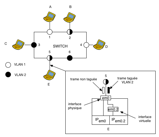
On a host, we define the concept of a virtual interface: we can create one or several virtual interfaces belonging to different VLANs on a given physical network interface.
Each virtual interface will be used to transmit and receive tagged frames.
When creating a virtual interface, we specify its name (e.g. em0.2), the
tag, or the VLAN number as well as the physical network interface on which
traffic will be transmitted.
Virtual interfaces are configured as conventional Ethernet interfaces. Thus, all frames transmitted on a virtual interface will automatically be tagged with the VLAN associated with this interface.
For example: host E has 2 interfaces: a physical interface em0
to handle untagged frames and a virtual interface em0.2
for tagged frames belonging to VLAN 2.
When interface em0 receives a tagged frame, it determines
the membership of a VLAN based on the tag, removes the tag, and
forwards it to the virtual interface associated with this VLAN.
3 Transport Layer
In this part, we consider the Transport Layer with two main protocols: TCP and UDP.
3.1 Transport
The transport layer supports data transfer between two processes on two hosts interconnected through the network layer.
Transport addresses are ports - they serve to identify the processes that exchange data.
The IP layer introduces imperfections: packets may be lost, may arrive in disorder, may contain corrupted data.
The objective of the transport layer is to support data transfer with the required quality of service, for instance sufficient reliability and ordered transfer.
3.1.1 Reliable data transfer
There are several techniques for guaranteeing reliable data transfer:
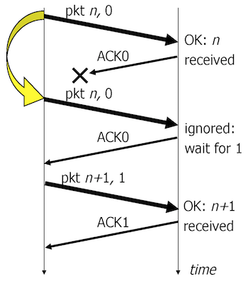
- Send and Wait. The sender sends a data segment and waits for an ACK (Acknowledgement - confirmation of a good reception of the segment). Requires 1 send buffer and 1 receive buffer. Low performance for large bandwidth-delay products.
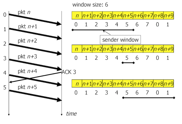
- Sliding Window. To improve the performance, the sender has a possibility of sending several segments (a window \(W\) segments) without waiting for ACKs. In this way, the sender can transmit all the time, if the window is sufficiently large.
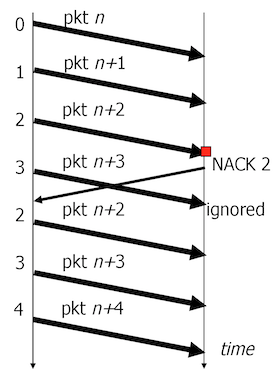
- Go-back-N. In case of a lost segment, the sender retransmits all segments starting from the missing segment. Requires \(W\) send buffers (\(W\) - window) and 1 receive buffer. May result in low performance because of the segments that are unnecessarily retransmitted.
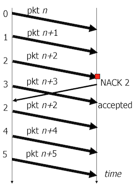
- Selective Retransmit. In case of a lost segment, the sender only retransmits the missing segment. Requires \(W\) send buffers and \(W\) receive buffers. Achieves the best performance, but more complex to implement.
3.1.2 Flow control
Data segments arriving to the receiver buffer may be overwritten if the application process does not read the data sufficiently fast. The objective of the flow control is to notify and possibly block the sender, if the receiver does not have sufficient buffer space for receiving data.
Credit based flow control. The receiver announces the sliding window to the sender with the value that corresponds to the current state of free buffers. The announced window of 0 means that there is no place in the receiver buffer so the sender cannot send more data.
3.2 TCP (Transmission Control Protocol)
TCP (Transmission Control Protocol) offers a reliable byte stream transfer with credit based flow control. Reliability relies on a sliding window, loss detection at the sender on timeouts and go-back-N retransmissions of lost segments. Optimization called "Fast Retransmit" results in a scheme similar to the selective retransmission with the detection at the sender: 3 duplicated ACKs indicate a lost segment that should be retransmitted.
3.2.1 TCP segment
 0                   1                   2                   3
 0 1 2 3 4 5 6 7 8 9 0 1 2 3 4 5 6 7 8 9 0 1 2 3 4 5 6 7 8 9 0 1
+-+-+-+-+-+-+-+-+-+-+-+-+-+-+-+-+-+-+-+-+-+-+-+-+-+-+-+-+-+-+-+-+
|          Source Port          |       Destination Port        |
+-+-+-+-+-+-+-+-+-+-+-+-+-+-+-+-+-+-+-+-+-+-+-+-+-+-+-+-+-+-+-+-+
|                        Sequence Number                        |
+-+-+-+-+-+-+-+-+-+-+-+-+-+-+-+-+-+-+-+-+-+-+-+-+-+-+-+-+-+-+-+-+
|                    Acknowledgment Number                      |
+-+-+-+-+-+-+-+-+-+-+-+-+-+-+-+-+-+-+-+-+-+-+-+-+-+-+-+-+-+-+-+-+
|  Data |           |U|A|P|R|S|F|                               |
| Offset| Reserved  |R|C|S|S|Y|I|            Window             |
|       |           |G|K|H|T|N|N|                               |
+-+-+-+-+-+-+-+-+-+-+-+-+-+-+-+-+-+-+-+-+-+-+-+-+-+-+-+-+-+-+-+-+
|           Checksum            |         Urgent Pointer        |
+-+-+-+-+-+-+-+-+-+-+-+-+-+-+-+-+-+-+-+-+-+-+-+-+-+-+-+-+-+-+-+-+
|                    Options                    |    Padding    |
+-+-+-+-+-+-+-+-+-+-+-+-+-+-+-+-+-+-+-+-+-+-+-+-+-+-+-+-+-+-+-+-+
|                             data                              |
+-+-+-+-+-+-+-+-+-+-+-+-+-+-+-+-+-+-+-+-+-+-+-+-+-+-+-+-+-+-+-+-+
- Source and destination ports
- Numbers on 16 bits to identify the source and the destination process.
- Sequence number
- Number on 32 bits. The number of the first byte in the segment in the data stream.
- Acknowledgment number
- Number on 32 bits. If the ACK flag is set, it indicates the number of the expected byte in the data stream. Confirms the good reception of all bytes with the numbers less than the acknowledgment number.
- Data offset
- The size of the header in 32 bit words. The header may have optional fields so we need the information of its size.
- Flags
- URG
- urgent pointer valid
- ACK
- acknowledgment number valid
- PSH
- tells TCP to push buffered data to application
- RST
- resets the connection in case of anomalies
- SYN
- initializes a connection by synchronizing sequence numbers
- FIN
- finish sending data
- Window
- The number of bytes the receiver can accept.
- Checksum
- 16 bit one's complement of the one's complement sum of all 16 bit words computed on the TCP segment with the pseudo header prepended. This pseudo header contains the IP source address, the IP destination address, the protocol, and the TCP length.
- Urgent pointer
- A positive offset from the sequence number, pointing to the byte following the urgent data.
- Options
- MSS (Maximum Segment Size) - proposed segment size for the connection (only in SYN segment). The chosen MSS is the minimum of the proposals of the sender and the receiver.
What is MSS ?
The largest amount of data that computer or communications device can receive in a single TCP segment is measured by the maximum segment size (MSS) in bytes.
3.2.2 Connection establishment and termination
A client and a server establish a connection with the initial exchange of 3 segments, three-way handshake:
- SYN segment (only TCP header with flag SYN and SEQ field set): the client proposes its sequence number SEQ=\(x\),
- SYN, ACK segment: the server acknowledges with ACK=\(x+1\) (it waits for byte \(x+1\)) and proposes its sequence number SEQ=\(y\),
- ACK segment: the client acknowledges with ACK=\(y+1\) (it waits for byte \(y+1\)).
Any end point (client or server) can close the connection by sending a segment with FIN flag set. The other end point confirms with an ACK and can close the connection in the opposite direction: a segment with FIN set and the ACK.
TCP end points negotiate the maximum segment size (MSS) in bytes (a typical value is 1460 B that fits the maximal size of the Ethernet frame of 1500 B, IP and TCP headers included).
3.2.3 Data transfer
After connection establishment both end points can send data following the principles (data transfer in one direction):
- Sequence number SEQ=\(x_1\), \(x_1\) is the number of the first byte in the data field, the length of the data field is LEN=\(l_1\),
- The next segment will have SEQ=\(x_1+l_1\),
- The TCP ACK segment for the first segment will have ACK=\(x_1+l_1\).
Example:
- 1st segment SEQ=100, LEN=10
- 2nd segment SEQ=110, LEN=20
- 3rd segment SEQ=130, LEN=10
- ACK for the 1st segment: ACK=110
- ACK for the 2nd segment: ACK=130
- ACK for the 3rd segment: ACK=140
If the both end points have data to send in opposite directions, acknowledgements are not sent in separate segments, but the right value of ACK is set in a data segment ("piggybacking"). Every segment thus contains a sequence number SEQ (for sending data), plus an ack number ACK (for the reverse direction). Example:
- sending segment SEQ=100, ACK=1100, LEN=10
- receiving segment SEQ=1100, ACK=110, LEN=50
- sending segment SEQ=110, ACK=1150, LEN=10
- receiving segment SEQ=1150, ACK=120, LEN=50
3.2.4 Flow control
The receiver announces the current window to the sender in the Window (WND) field. The sender stores this value in variable \(rwnd\). Upon receiving a segment with ACK=\(j\) and WND=\(k\), the sender can send data until byte number \(j + k - 1\).
Example: when received a segment with ACK=1000, WND=3000, the sender can send:
- 1st segment SEQ=1000, LEN=1000
- 2nd segment SEQ=2000, LEN=1000
- 3rd segment SEQ=3000, LEN=1000
Upon the reception of WND=0, the sender cannot send any data segment. If the sender has data to send, it probes the receiver with a segment containing one data byte past the end of the window (after a Persist Timer).
Why is the receive window WND needed?
Because it allows the sender not to overflow its receiver.
What is the maximum size of rwnd?
64KB (unless using RFC 1323 for the scaling option that allows increasing the window).
3.2.5 Error control
TCP uses a sliding window protocol with retransmission of lost segments. The sender detects losses by timeout: it associates a RTO time with each unacknowledged segment. If the timer expires, it retransmits the first unacknowledged segment and resets all timers for other segments (Reno variant). Earlier implementations (Tahoe) did not reset the pending timers after a timeout (Tahoe implements the Go-Back-N protocol). As isolated losses are more probable, Reno only retransmits the first segment.
Fast Retransmit: if 3 duplicate ACKs for the same bytes are received before the retransmission timeout, the sender retransmits the first unacknowledged segment. Fast Retransmit speeds up retransmission because usually the round trip time is shorter than RTO.
Upon a data segment reception, a TCP receiver may:
- send an acknowledgement immediately,
- wait until there is a data segment to send (Delayed ACK), or
- wait until other segments are received, because ACKs are cumulative.
The TCP receiver should immediately send an ACK when it receives out of order segments (there is a gap in the received data), which generates a duplicate ACK - the ACK will confirm the previously acknowledged data.
Waiting for a data segment to send in the opposite direction is limited by the delayed ACK timer (typical value of 200 ms): if it expires, an ACK is sent.
3.2.6 Retransmission timer
When TCP sends a segment, it starts a timer. If the timer expires before it receives an acknowledgment, it retransmits the segment ("timeout"). As the timeout should be longer the round-trip time (RTT), TCP needs to estimate the current RTT.
Algorithm for RTT estimation.
RTT = 0, D = 3
RTO = RTT + 2 * D = 0 + 2 * 3 = 6 (for initial SYN)

RTT = RTT + g * (measured_RTT - RTT) (g = 1/8)
D = D + h * (|measured_RTT - RTT| - D) (h = 1/4)
RTO = RTT + 4 * D

If (a segment has been retransmitted after a timeout)
    ; apply exponential backoff:
    RTO = min(2*RTO, 64 sec)
    RTT and D are not updated
3.3 TCP Congestion Control
Congestion arises when a source host transmits at the rate that exceeds the capacity of the network (in fact the capacity of a bottleneck link on the route between the source and the destination). Congestion results in lost packets, wasted network resources, and a lower overall throughput. Congestion Control addresses this problem by adjusting the rate of injecting packets in the network to avoid inefficient operation.
3.3.1 Principles
A TCP source needs to adapt its data sending rate to the capacity of bottleneck links. The bottleneck link is the link on the route between the source and the destination on which the TCP connection obtains the smallest capacity in contention with other connections that share the link. A TCP source tries to approach, but not to exceed the capacity of the network.
TCP uses the AIMD (Additive Increase Multiplicative Decrease) control algorithm:
- increase the rate in an additive way, if there is no congestion
- decrease the rate in an multiplicative way in case of congestion
TCP interprets segment losses as the congestion signal.
What is a bottleneck link?
The link on which the TCP connection obtains the smallest capacity in contention with other connections that share the link.
Why are bottleneck links important for a TCP source ?
A TCP source has to adapt its data sending rate to the capacity that it can obtain on a bottleneck link.
What is Additive Increase and when it is used?
Increase the rate in an additive way (add a constant value), if there is no congestion.
What is Multiplicative Decrease and when it is used?
Decrease the rate in an multiplicative way (multiply by a fraction value) in case of congestion.
3.3.1.1 Congestion Window
TCP controls the sending rate by adjusting the Congestion Window (\(cwnd\)) in octets.
The current sending window \(W\) is modulated by the congestion control algorithms through \(cwnd\) or flow control through \(rwnd\) (remember that \(rwnd\), the Receive Window in octets contains the window advertised by the TCP receiver corresponding to the free buffer space):
- \(W = min (cwnd, rwnd)\).
In the examples of Congestion Control, we assume that \(rwnd\) is sufficiently large so \(cwnd\) limits \(W\).
What happens when the receiver advertises a sufficiently large window?
The sending window is limited by congestion control.
3.3.1.2 TCP variants
From the congestion control point of view, TCP evolved over time. Several variants have been defined: Tahoe, Reno, New Reno, Vegas. More recent variants include: BIC, CUBIC, Compound, and many more. Tahoe is the simplest variant with two states: Slow Start and Congestion Avoidance. Reno adds Fast Recovery.
What are the congestion control states defined by Tahoe?
Slow Start and Congestion Avoidance.
What are the congestion control states defined by Reno?
Slow Start, Congestion Avoidance, and Fast Recovery.
3.3.1.3 Slow Start
Slow Start algorithm:
ssthresh = 64KB
cwnd = 1 * MSS (initial value depends on implementation and it may go up to 3 MSS)
increase cwnd by 1 MSS for each received ACK, which results in exponential
increase: 1, 2, 4, 8 MSS etc.

if packet loss on timeout, apply Multiplicative Decrease:
   ssthresh = cwnd / 2 (but not less than 2MSS)
     reenter Slow Start

if cwnd >= sshtresh, enter Congestion Avoidance
ssthresh corresponds to the threshold that a TCP source tries to attain: TCP probes for the bottleneck capacity by progressively increasing the congestion window until:
- a loss - reenter Slow Start or
- cwnd >= sshtresh, enter Congestion Avoidance.
What is the Slow Start algorithm?
Slow Start algorithm:
- exponential increase until cwnd >= sshtresh, then
- enter Congestion Avoidance
- if loss, apply Multiplicative Decrease:
- ssthresh = cwnd / 2 (but not less than 2MSS)
- cwnd = 1 * MSS
- reenter Slow Start (cwnd = 1MSS)
- ssthresh = cwnd / 2 (but not less than 2MSS)
What is Multiplicative Decrease?
A way of decreasing the congestion window after loss detection. It consists of setting ssthresh to the half of the current value of cwnd.
What is Exponential Increase?
A way of increasing the congestion window: adding 1 MSS to cwnd for each received ACK. It is used in Slow Start and in Fast Recovery.
3.3.1.4 Congestion Avoidance
Congestion Avoidance algorithm:
apply Additive Increase:
- add 1 MSS to cwnd for the whole correctly received window, which results
in linear increase: 10, 11, 12 MSS etc.
- actual adjusting of cwnd takes place for each received ACK:
  - cwnd increases by MSS×MSS/cwnd for each ACK

if packet loss on timeout, apply Multiplicative Decrease:
   - ssthresh = cwnd / 2 (but not less than 2MSS)
     - cwnd = 1 * MSS
     - reenter Slow Start
What happens in the Congestion Avoidance state ?
Congestion Avoidance algorithm:
- increase cwnd linearly:
- adds 1 MSS for a window (in fact: cwnd increases by MSS×MSS/cwnd for each ACK).
- if loss, adjust threshold:
- ssthresh = cwnd / 2 (but not less than 2MSS)
- reenter Slow Start (cwnd = 1MSS)
What is Additive Increase?
A way of increasing the congestion window when there is no segment loss. It consists of adding 1 MSS to cwnd when TCP receives ACKs for the whole window: 5, 6, 7, etc. (actual adjusting of cwnd takes place for each received ACK: cwnd increases by MSS×MSS/cwnd).
3.3.1.5 Fast Retransmit
When TCP receives 3 duplicated ACKs, it considers them as a signal of a packet loss and reenters Slow Start (Tahoe) or enters Fast Recovery (Reno, New Reno).
What is TCP Fast Retransmit ?
When TCP receives 3 duplicated ACKs, it considers them as a signal of a packet loss and re-enters Slow Start (Tahoe) or enters Fast Recovery (Reno, New Reno).
3.3.1.6 Fast Recovery
Fast Recovery algorithm:
retransmit missing segment
apply Multiplicative Decrease:
- ssthresh = cwnd / 2 (but not less than 2MSS)
inflate cwnd to compensate for the loss detection with 3 duplicate ACKs:
  - cwnd = ssthresh + 3MSS
for each duplicate ACK:
  - cwnd = cwnd + 1MSS
if ACK received for the lost segment
   enter Congestion Avoidance with cwnd = sstresh.
Why inflate cwnd by 3MSS?
To compensate for 3 segments sent that generate duplicate ACKs after a loss.
3.3.2 UDP
 0                   1                   2                   3
 0 1 2 3 4 5 6 7 8 9 0 1 2 3 4 5 6 7 8 9 0 1 2 3 4 5 6 7 8 9 0 1
+-+-+-+-+-+-+-+-+-+-+-+-+-+-+-+-+-+-+-+-+-+-+-+-+-+-+-+-+-+-+-+-+
|          Source Port          |       Destination Port        |
+-+-+-+-+-+-+-+-+-+-+-+-+-+-+-+-+-+-+-+-+-+-+-+-+-+-+-+-+-+-+-+-+
|            Length             |           Checksum            |
+-+-+-+-+-+-+-+-+-+-+-+-+-+-+-+-+-+-+-+-+-+-+-+-+-+-+-+-+-+-+-+-+
|                                                               |
|                             Data                              |
|                                                               |
+-+-+-+-+-+-+-+-+-+-+-+-+-+-+-+-+-+-+-+-+-+-+-+-+-+-+-+-+-+-+-+-+
- Source and destination ports
- Numbers on 16 bits to identify the source and the destination process.
- Length
- is the length in octets of this user datagram including this header and the data. (This means the minimum value of the length is eight.)
- Checksum
- 16 bit one's complement of the one's complement sum of all 16 bit
words computed on the UDP segment with the pseudo header prepended. The
pseudo header conceptually prefixed to the UDP header contains the IP source
address, the IP destination address, the protocol, and the UDP length.
UDP does not provide reliability nor ordered transfer as TCP, but rather support a request-response way of operation. If a UDP segment is received, the checksum indicates the absence of transmission errors. Losses may happen though.
3.3.3 NAT (Network Address Translation)
NAT provides a means for using private IP addresses in a part of the network (Intranet). Such a network uses one public IP address and one or several prefixes taken from the reserved part of the addressing space (10/8, 192.168/16 etc.).
To forward packets to the hosts with private addresses, a NAT router maintains a table for Address and Port Forwarding:
+-+-+-+-+-+-+-+-+-+-+-+-+-+-+-+-+-+-+-+-+-+-+-+-+-+-+-+
|             private part           |   public part  |
+-+-+-+-+-+-+-+-+-+-+-+-+-+-+-+-+-+-+-+-+-+-+-+-+-+-+-+
| private IP address, private port # | public port #  |
+-+-+-+-+-+-+-+-+-+-+-+-+-+-+-+-+-+-+-+-+-+-+-+-+-+-+-+
When the NAT router receives an IP packet with:
- source IP address, source port, e.g.
10.0.0.1and51234
it replaces them with:
- public source IP address, public source port, e.g.
129.88.48.1and58765
When the NAT router receives the response packet with:
- destination IP address, destination port, e.g.
129.88.48.1and58765
it looks up the table for the matching port and replaces the destination IP address and the destination port with the values from the table:
- private destination IP address, private destination port, e.g.
10.0.0.1and51234
It the forward the packet to the destination host on the Intranet.
To reach the hosts on the Intranet from the Internet, NAT routers use "port forwarding": they maintain a table of ports associated with hosts on the Intranet, e.g.:
+-+-+-+-+-+-+-+-+-+-+-+-+-+-+-+-+-+-+-+-+-+-+-+
|          range        | private IP address  |
+-+-+-+-+-+-+-+-+-+-+-+-+-+-+-+-+-+-+-+-+-+-+-+
|        6800-6899      |      10.0.0.1       |
|        6900-6999      |      10.0.0.2       |
+-+-+-+-+-+-+-+-+-+-+-+-+-+-+-+-+-+-+-+-+-+-+-+
A host on the Internet sends a packet to the public address and the
destination port corresponding to a given range, e.g. 129.88.48.1 and 6910
to reach host 10.0.0.2 (a given service to reach needs to run over the
chosen port, e.g. ssh deamon on port 6910, if we want to connect to 10.0.0.2
with ssh).
4 Application Layer - Naming
Name: information that identifies an entity, often in a form understandable by humans. The difference between an address and a name: an address tells how to reach an entity while a name identifies it.
4.1 DNS (Domain Name System)
DNS maintains a global worldwide directory of names that allows you to find an IP address associated with a name.
DNS consists of a set of servers distributed in a hierarchical way around the world.
DNS names:
- hierarchical structure in the form of the tree in which nodes correspond to
labels of up to 63 characters (letters, numbers, "-", uppercase or lowercase
does not matter: IMAG.FR = imag.fr = ImAG.fR).
- root: designated with "
." to which correspond 13 root servers distributed over the world, - DNS name: a list of labels separated by dots, for example:
drakkar.imag.fr. - Fully Qualified Domain Name (FQDN): a DNS name with the endpoint (e.g.
drakkar.imag.fr.). The full domain name may not exceed the length of 253 characters. - local name, for example:
delos(interpreted with respect to a given local domain, imag.fr in this example:delos.imag.fr)
DNS Tree (Top Level Domains, TLD) :
- generic domains (gTLD):
com,edu,gov,net,org,arpa. And also:academy,adult,biz,food,info,mobi,name,travel. - country domains (ccTLD):
fr,uk,us,io,co,me,ru,p.
- root: designated with "
4.2 Name Administration
DNS names are managed by zones:
- zone (example:
mit.edu,lcs.mit.edu,imag.fr), a managed subtree managed separately by the owner of the domain (management is delegated to the zoned). Each zone manager can create or destroy names or sub-zone (and delegate), - a zone must operate at least one name server (DNS service on
port
53), - redundancy for reliability: primary server, secondary (copy of the primary server).
4.3 DNS Database
A DNS name server maintains:
- the master database of the zone containing RR records
(Resource Record):
- names in the zone (to provide the "authoritative response" coming from the official server of the zone)
- pointers to name servers in sub-zones
- serial number: counter of updates (versions)
- the database is read by the DNS server at startup
A zone has one or more name servers that maintain the same copy of the database.
The name servers (primary/secondary) have a dual function:
- manage the base of the names of their zone, answer queries,
- respond to name resolution queries in their zone (an entry point to the rest of the DNS system) and manage the cache of the replies coming from DNS servers to accelerate name resolution (the answers coming from the cache are "non-authoritative").
Here is the beginning of the definition of the imag.fr domain:
$ORIGIN .
$TTL 7200	; 2 hours
imag.fr			IN SOA	imag.imag.fr. fr-imag-subdom-admin.imag.fr. (
                2003032401 ; serial
                21600      ; refresh (6 hours)
                3600       ; retry (1 hour)
                3600000    ; expire (5 weeks 6 days 16 hours)
                86400      ; minimum (1 day)
                )
            NS	dns.inria.fr.
            NS	ns2.nic.fr.
            NS	imag.imag.fr.
            NS	isis.imag.fr.
            A	129.88.30.1
            MX	10 imag.imag.fr.
            MX	20 harmonie.imag.fr.
            MX	50 ebene.inrialpes.fr.
            TXT	"IMAG  BP 53  F-38041 GRENOBLE Cedex 9 (France)"
            TXT	"Institut d'Informatique et de Mathematiques Appliquees"
            TXT	"or IMAG 46 Av. Felix Viallet  F-38031 GRENOBLE
            Cedex 1"
What are the name servers of the domain?
DNS name servers are:
NS imag.imag.fr.
NS isis.imag.fr.
A copy of the database is also maintained by Inria and NIC:
NS dns.inria.fr.
NS ns2.nic.fr.
4.4 DNS records
The DNS database is composed of records - RR (Resource Record).
Several types exist:
- A: couple of name - IP address (IPv4: 4 bytes in decimal notation)
- AAAA: couple of name - IPv6 address (128 bits in hexadecimal notation)
- PTR: couple of IP address - name (the name is stored as the label
attached to a special domain
in-addr.arpaby inverting the byte order:94.38.88.129.in-addr.arpacorresponds to address129.88.38.94), - CNAME: canonical name for an alias
- NS: the name server of the domain
- HINFO: info on the host
- MX: mail server for the domain
- SOA: marks the beginning of a zone (Start of Authority)
- SRV: indicates available services (protocol and port number).
Recall what RR means in DNS, the origin of the terminology and the information RR may contain.
RR: Resource Record are records a DNS database.
Each RR has a type (A, NS, CNAME etc.), a
DNS name (for example web.ensimag.fr or imag.fr), and associated information
according to a given type (e.g. class of address, address itself for type A,
names of a DNS server for the NS type like imag.fr).
In the traffic capture while accessing a web page:
Time      Source         Destination    Prot. Info
0.004187  130.190.123.77 193.54.188.33  DNS   Standard query 0x9e63 A web.ensimag.fr
0.007218  193.54.188.33  130.190.123.77 DNS   Standard query response 0x9e63
                                          CNAME web-ensimag.imag.fr A 195.221.228.24
The DNS response includes 2 "Answers":
Answers
    web.ensimag.fr: type CNAME, class IN, cname web-ensimag.imag.fr
    web-ensimag.imag.fr: type A, class IN, addr 195.221.228.24
Why 2 "Answers" and not just one?
Because the question was about a name that was not a canonical name (web.ensimag.fr). So, the
response gives the canonical name (response to a query on CNAME RR) and the address
associated with this canonical name (RR of type A).
4.5 Name Resolution
It is the process of finding a record that matches a query,
for example: what is the address that corresponds to the name drakkar.imag.fr,
RR of type A?
- iterative query:
- we send the request to the root server that will indicate the DNS server to use,
- we then send the request to the DNS server that either provides the response, or indicates another DNS server to use,
- this phase is repeated until we obtain the response of the DNS server of the domain.
- recursive query:
- we send the request to a DNS server that handles name resolution and provides the answer.
What is the meaning of this DNS query?
dig NS .
We look for the name server (RR of type NS) of the root of the DNS tree
(name to resolve is "."). So we look for the root servers:
dig NS .

;; QUESTION SECTION:
;.				IN	NS

;; ANSWER SECTION:
.			4431	IN	NS	a.root-servers.net.
.			4431	IN	NS	b.root-servers.net.
.			4431	IN	NS	c.root-servers.net.
.			4431	IN	NS	d.root-servers.net.
.			4431	IN	NS	e.root-servers.net.
.			4431	IN	NS	f.root-servers.net.
.			4431	IN	NS	g.root-servers.net.
.			4431	IN	NS	h.root-servers.net.
.			4431	IN	NS	i.root-servers.net.
.			4431	IN	NS	j.root-servers.net.
.			4431	IN	NS	k.root-servers.net.
.			4431	IN	NS	l.root-servers.net.
.			4431	IN	NS	m.root-servers.net.
What is the meaning of this DNS query?
dig NS com.
We look for the name server of the com. domain:
dig NS com.

;; QUESTION SECTION:
;com.				IN	NS

;; ANSWER SECTION:
com.			90885	IN	NS	m.gtld-servers.net.
com.			90885	IN	NS	j.gtld-servers.net.
com.			90885	IN	NS	l.gtld-servers.net.
com.			90885	IN	NS	g.gtld-servers.net.
com.			90885	IN	NS	b.gtld-servers.net.
com.			90885	IN	NS	h.gtld-servers.net.
com.			90885	IN	NS	a.gtld-servers.net.
com.			90885	IN	NS	i.gtld-servers.net.
com.			90885	IN	NS	d.gtld-servers.net.
com.			90885	IN	NS	c.gtld-servers.net.
com.			90885	IN	NS	f.gtld-servers.net.
com.			90885	IN	NS	k.gtld-servers.net.
com.			90885	IN	NS	e.gtld-servers.net.
What is the meaning of this DNS query?
dig SOA .
We're looking for the institution that manages the root DNS .:
dig SOA .

;; QUESTION SECTION:
;.				IN	SOA

;; ANSWER SECTION:
.			81204	IN	SOA
a.root-servers.net. nstld.verisign-grs.com. 2015011700 1800 900 604800 86400
The root is managed by Verisign.
4.6 Reverse Resolution
It is the process of finding the domain name associated with an IP address,
for example: what is the name that corresponds to address 129.88.48.22?
The reverse resolution is based on the PTR record and the domain
in-addr.arpa.
To find the domain name of IP address 129.88.48.22, we resolve the
name by representing the address bytes in the reverse order:
2.174.198.91.in-addr.arpa.
For example:
dig PTR 22.48.88.129.in-addr.arpa

;; ANSWER SECTION:
22.48.88.129.in-addr.arpa. 86400 IN	PTR	delos.imag.fr.

;; AUTHORITY SECTION:
88.129.in-addr.arpa.	18439	IN	NS	imag.imag.fr.
88.129.in-addr.arpa.	18439	IN	NS	isis.imag.fr.
88.129.in-addr.arpa.	18439	IN	NS	ns2.nic.fr.
88.129.in-addr.arpa.	18439	IN	NS	dns.inria.fr.
88.129.in-addr.arpa.	18439	IN	NS	ns.ripe.net.
The response part indicates that it is delos.imag.fr that has the address 129.88.48.22.
The authority part indicates what are the nameservers of the imag.fr domain.
To be able to make updates in the database, the owner of an
address block (prefix) as for example 129.88/16 has the right to modify
the 88.129.in-addr.arpa zone, which is shown in the authority section of the response:
dig SOA 22.48.88.129.in-addr.arpa

;; QUESTION SECTION:
;22.48.88.129.in-addr.arpa.	IN	SOA

;; AUTHORITY SECTION:
88.129.in-addr.arpa.	86400	IN	SOA
imag.imag.fr. fr-imag-subdom-admin.imag.fr. 2015011602 21600 3600 3600000 86400